1.3.c Interpret packet capture
1.3.c (i) Using Wireshark trace analyzer
1.3.c (ii) Using IOS embedded packet capture
Sunday, February 5, 2017
1.3.b Apply troubleshooting methodologies
1.3.b Apply troubleshooting methodologies
1.3.b (i) Diagnose the root cause of networking issue (analyze symptoms, identify and describe root cause)
1.3.b (ii) Design and implement valid solutions according to constraints
1.3.b (iii) Verify and monitor resolution
http://www.ciscopress.com/articles/article.asp?p=1578504&seqNum=2
A good problem description consists of accurate descriptions of symptoms and not of interpretations or conclusions. Consequences for the user are strictly not part of the problem description itself, but can be helpful to assess the urgency of the issue. When a problem is reported as "The mail server isn't working," you must perhaps contact the user and find out exactly what he has experienced. You will probably define the problem as "When user X starts his e-mail client, he gets an error message saying that the client can not connect to the server. The user can still access his network drives and browse the Internet."
1.3.b (i) Diagnose the root cause of networking issue (analyze symptoms, identify and describe root cause)
1.3.b (ii) Design and implement valid solutions according to constraints
1.3.b (iii) Verify and monitor resolution
http://www.ciscopress.com/articles/article.asp?p=1578504&seqNum=2
- Gathering information: Gathering information happens after the problem has been reported by the user (or anyone). This might include interviewing all parties (user) involved, plus any other means to gather relevant information. Usually, the problem report does not contain enough information to formulate a good hypothesis without first gathering more information. Information and symptoms can be gathered directly, by observing processes, or indirectly, by executing tests.
- Analyzing information: After the gathered information has been analyzed, the troubleshooter compares the symptoms against his knowledge of the system, processes, and baselines to separate normal behavior from abnormal behavior.
- Eliminating possible causes: By comparing the observed behavior against expected behavior, some of the possible problems causes are eliminated.
- Formulating a hypothesis: After gathering and analyzing information and eliminating the possible causes, one or more potential problem causes remain. The probability of each of these causes will have to be assessed and the most likely cause proposed as the hypothetical cause of the problem.
- Testing the hypothesis: The hypothesis must be tested to confirm or deny that it is the actual cause of the problem. The simplest way to do this is by proposing a solution based on this hypothesis, implementing that solution, and verifying whether this solved the problem. If this method is impossible or disruptive, the hypothesis can be strengthened or invalidated by gathering and analyzing more information.
A good problem description consists of accurate descriptions of symptoms and not of interpretations or conclusions. Consequences for the user are strictly not part of the problem description itself, but can be helpful to assess the urgency of the issue. When a problem is reported as "The mail server isn't working," you must perhaps contact the user and find out exactly what he has experienced. You will probably define the problem as "When user X starts his e-mail client, he gets an error message saying that the client can not connect to the server. The user can still access his network drives and browse the Internet."
- Top down: Using this approach, you work from the Open Systems Interconnection (OSI) model's application layer down to the physical layer.
- Bottom up: The bottom-up approach starts from the OSI model's physical layer and moves up to the application layer.
- Divide and conquer: Using this approach, you start in the middle of the OSI model's stack (usually the network layer) and then, based on your findings, you move up or down the OSI stack.
- Follow the path: This approach is based on the path that packets take through the network from source to destination.
- Spot the differences: As the name implies, this approach compares network devices or processes that are operating correctly to devices or processes that are not operating as expected and gathers clues by spotting significant differences. In case the problem occurred after a change on a single device was implemented, the spot-the-differences approach can pinpoint the problem cause by focusing on the difference between the device configurations, before and after the problem was reported.
- Move the problem: The strategy of this troubleshooting approach is to physically move components and observe whether the problem moves with the components.
1.3.a (iv) Performance monitor
1.3.a Use IOS troubleshooting tools
1.3.a (i) debug, conditional debug
1.3.a (ii) ping, traceroute with extended options
1.3.a (iii) Embedded packet capture
1.3.a (iv) Performance monitor
Cisco Performance Monitor enables you to monitor the flow of packets in your network and become aware of any issues that might impact the flow before it starts to significantly impact the performance of the application in question. Performance monitoring is especially important for video traffic because high quality interactive video traffic is highly sensitive to network issues. Even minor issues that may not affect other applications can have dramatic effects on video quality.
Because Cisco Performance Monitor uses similar software components and commands as Cisco NetFlow and Cisco Flexible NetFlow, familiarity with these products will help you to understand how to configure Cisco Performance Monitor. These products provide statistics on packets flowing through a router and are the standard for acquiring IP operational data from IP networks. They provide data to support network and security monitoring, network planning, traffic analysis, and IP accounting. For more information about Cisco NetFlow and Cisco Flexible NetFlow, see the documents listed in the Additional References section.
The following prerequisites must be met before you can configure Cisco Performance Monitor:
To configure Cisco Performance Monitor, configure many of the same basic elements that you normally configure for Flexible NetFlow:
The figure below shows how these elements are related to each other. The elements at the bottom of the figure are configured first.
Figure 1. Cisco Performance Monitor Components
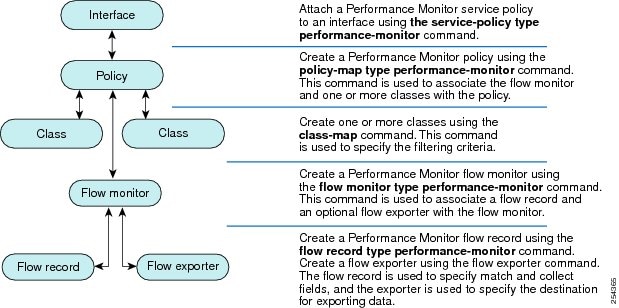
As shown above, a policy includes one or more classes. Each class has a flow monitor associated with it, and each flow monitor has a flow record and an optional flow exporter associated with it. These elements are configured in the following order:
You can monitor the following information by configuring a flow record with collect or match commands for the corresponding non-key fields:
Cisco Performance Monitor provides support for the use of the industry-standard Simple Network Management Protocol (SNMP) to monitor media streams. This support is implemented with the addition of the following Cisco proprietary SNMP Management Information Base (MIB) modules:
This feature also includes two new command-line interface (CLI) commands and one modified CLI command. The commands are as follows:
1.3.a (i) debug, conditional debug
1.3.a (ii) ping, traceroute with extended options
1.3.a (iii) Embedded packet capture
1.3.a (iv) Performance monitor
http://www.cisco.com/c/en/us/td/docs/ios-xml/ios/media_monitoring/configuration/15-mt/mm-15-mt-book/mm-pasv-mon.html
Overview of Cisco Performance Monitor
Because Cisco Performance Monitor uses similar software components and commands as Cisco NetFlow and Cisco Flexible NetFlow, familiarity with these products will help you to understand how to configure Cisco Performance Monitor. These products provide statistics on packets flowing through a router and are the standard for acquiring IP operational data from IP networks. They provide data to support network and security monitoring, network planning, traffic analysis, and IP accounting. For more information about Cisco NetFlow and Cisco Flexible NetFlow, see the documents listed in the Additional References section.
Prerequisites for Configuring Cisco Performance Monitor
IPv4 Traffic
IPv6 Traffic
Configuration Components of Cisco Performance Monitor
The figure below shows how these elements are related to each other. The elements at the bottom of the figure are configured first.

- Configure a flow record to specify the key and non-key fields that you want to monitor. This is configured using match and collect commands. You can also optimally configure a flow exporter to specify the export destination. For Cisco Performance Monitor, you must configure a performance-monitor type flow record.
- Configure a flow monitor that includes the flow record and flow exporter. For Cisco Performance Monitor, you must configure a performance-monitor type flow monitor.
- Configure a class to specify the filtering criteria using the class-map command.
- Configure a policy to include one or more classes and one or more performance-monitor type flow monitors using the policy-map command. For Cisco Performance Monitor, you must configure performance-monitor type policies.
- Associate a performance-monitor type policy to the appropriate interface using the service-policy type performance-monitor command.
Data That You Can Monitor Using Cisco Performance Monitor
 Tip | For more information about these statistics, see the show performance monitor statuscommand in theCisco Media Monitoring Command Reference. |
- IP Packet Count
- IP TTL
- IP TTL minimum
- IP TTL maximum
- Flow to Interface Mapping
- IP Flow destination address and port, source address and port, and protocol
- RTP Synchronization Source (SSRC)
- IP Octets Count
- Media Stream Packet Count
- Media Stream Octect Count
- Media Byte Rate
- Media Byte Count
- Media Packet Rate
- Media Packet Loss Count
- Media Packet Loss Rate
- Packets Expected Count
- Measured Rate
- Media Loss Event Count
- Round Trip Time (RTT)
- Interarrival Jitter (RFC3550) max
- Interarrival Jitter (RFC3550) min 2
- Interarrival Jitter (RFC3550) mean
- Media Rate Variation
- Monitor Event
- Media Error
- Media Stop
- IP Byte Count
- IP Byte Rate
- IP Source Mask
- IP Destination Mask
- Epoch of A Monitoring Interval
- Packet Forwarding Status
- Packet Drops
- DSCP and IPv6 Traffic Class
SNMP MIB Support for Cisco Performance Monitor
- CISCO-FLOW-MONITOR-TC-MIB—Defines the textual conventions common to the following MIB modules.
- CISCO-FLOW-MONITOR-MIB—Defines the framework that describes the flow monitors supported by a system, the flows that it has learned, and the flow metrics collected for those flows.
- CISCO-RTP-METRICS-MIB—Defines objects that describe the quality metrics collected for RTP streams, similar to those described by an RTCP Receiver Report packet (RFC 3550).
- CISCO-IP-CBR-METRICS-MIB—Defines objects that describe the quality metrics collected for IP streams that have a Constant Bit Rate (CBR).
This feature also includes two new command-line interface (CLI) commands and one modified CLI command. The commands are as follows:
- snmp-server host—Enables the delivery of flow monitoring SNMP notifications to a recipient.
- snmp-server enable traps flowmon—Enables flow monitoring SNMP notifications. By default, flow monitoring SNMP notifications are disabled.
- snmp mib flowmon alarm history—Sets the maximum number of entries maintained by the flow monitor alarm history log.
1.3.a (iii) Embedded packet capture
1.3.a Use IOS troubleshooting tools
1.3.a (i) debug, conditional debug
1.3.a (ii) ping, traceroute with extended options
1.3.a (iii) Embedded packet capture
1.3.a (iv) Performance monitor
http://www.cisco.com/c/en/us/td/docs/ios-xml/ios/epc/configuration/15-mt/epc-15-mt-book/nm-packet-capture.html
Embedded Packet Capture (EPC) is an onboard packet capture facility that allows network administrators to capture packets flowing to, through, and from the device and to analyze them locally or save and export them for offline analysis by using a tool such as Wireshark. This feature simplifies network operations by allowing devices to become active participants in the management and operation of the network. This feature facilitates troubleshooting by gathering information about the packet format. This feature also facilitates application analysis and security.
Your software release may not support all the features documented in this module. For the latest caveats and feature information, see Bug Search Tool and the release notes for your platform and software release. To find information about the features documented in this module, and to see a list of the releases in which each feature is supported, see the feature information table at the end of this module.
Use Cisco Feature Navigator to find information about platform support and Cisco software image support. To access Cisco Feature Navigator, go to www.cisco.com/go/cfn. An account on Cisco.com is not required. The Embedded Packet Capture (EPC) software subsystem consumes CPU and memory resources during its operation. You must have adequate system resources for different types of operations. Some guidelines for using the system resources are provided in the table below.
Embedded Packet Capture (EPC) provides an embedded systems management facility that helps in tracing and troubleshooting packets. This feature allows network administrators to capture data packets flowing through, to, and from a Cisco device. The network administrator may define the capture buffer size and type (circular, or linear) and the maximum number of bytes of each packet to capture. The packet capture rate can be throttled using further administrative controls. For example, options allow for filtering the packets to be captured using an Access Control List and, optionally, further defined by specifying a maximum packet capture rate or by specifying a sampling interval. Some of the benefits of this feature include:
The capture buffer is an area in memory for holding the packet data. You can specify unique names, size and type of the buffer, and configure the buffer to handle incoming data as required.
The following types of data are stored in a capture buffer:
The metadata contains descriptive information about a set of packet data. It contains:
The capture point is a traffic transit point where a packet is captured and associated with a buffer. You can define capture points by providing unique names and different parameters.
The following capture points are available:
1.3.a (i) debug, conditional debug
1.3.a (ii) ping, traceroute with extended options
1.3.a (iii) Embedded packet capture
1.3.a (iv) Performance monitor
http://www.cisco.com/c/en/us/td/docs/ios-xml/ios/epc/configuration/15-mt/epc-15-mt-book/nm-packet-capture.html
Embedded Packet Capture (EPC) is an onboard packet capture facility that allows network administrators to capture packets flowing to, through, and from the device and to analyze them locally or save and export them for offline analysis by using a tool such as Wireshark. This feature simplifies network operations by allowing devices to become active participants in the management and operation of the network. This feature facilitates troubleshooting by gathering information about the packet format. This feature also facilitates application analysis and security.
- Finding Feature Information
- Prerequisites for Embedded Packet Capture
- Restrictions for Embedded Packet Capture
- Information About Embedded Packet Capture
- How to Implement Embedded Packet Capture
- Configuration Examples for Embedded Packet Capture
- Additional References
- Feature Information for Embedded Packet Capture
Finding Feature Information
Use Cisco Feature Navigator to find information about platform support and Cisco software image support. To access Cisco Feature Navigator, go to www.cisco.com/go/cfn. An account on Cisco.com is not required.
Prerequisites for Embedded Packet Capture
| Table 1 | System Requirements for the EPC Subsystem |
| System Resources | Requirements |
|---|---|
| Hardware | CPU utilization requirements are platform dependent. |
| Memory | The packet buffer is stored in DRAM. The size of the packet buffer is user specified. |
| Diskspace | Packets can be exported to external devices. No intermediate storage on flash disk is required. |
Restrictions for Embedded Packet Capture
- In Cisco IOS Release 12.2(33)SRE, EPC is supported only on 7200 platform.
- EPC only captures multicast packets on ingress and does not capture the replicated packets on egress.
- Currently, the capture file can only be exported off the device; for example, TFTP or FTP servers and local disk.
Embedded Packet Capture Overview
Benefits of EPC
- Ability to capture IPv4 and IPv6 packets in the Cisco Express Forwarding (CEF) path.
- A flexible method for specifying the capture buffer parameters.
- Filter captured packets.
- Methods to decode data packets captured with varying degree of detail.
- Facility to export the packet capture in PCAP format suitable for analysis using an external tool.
- Extensible infrastructure for enabling packet capture points.
Capture Buffer
The following types of data are stored in a capture buffer:
- Packet data
- Metadata
The metadata contains descriptive information about a set of packet data. It contains:
- A timestamp of when it is added to a buffer.
- The direction in which the packet data is transmitted--egress or ingress.
- The switch path captured.
- Encapsulation type corresponding to input or output interface to allow the decoding of L2 decoders.
- Define a capture buffer and associate it with a capture point.
- Clear capture buffers.
- Export capture buffers for offline analysis. Export writes off the file using one of the supported file transfer options: FTP, HTTP, HTTPS, PRAM, RCP, SCP, and TFTP.
- Display content of the capture buffers.
Capture Point
The following capture points are available:
- IPv4 CEF/interrupt switching path with interface input and output
- IPv6 CEF/interrupt switching path with interface input and output
- Associate or disassociate capture points with capture buffers. Each capture point can be associated with only one capture buffer.
- Destroy capture points.
- Activate packet capture points on a given interface. Multiple packet capture points can be made active on a given interface. For example, Border Gateway Protocol (BGP) packets can be captured into one capture buffer and Open Shortest Path First (OSPF) packets can captured into another capture buffer.
- Access Control Lists (ACLs) can be applied to capture points.
1.3.a (ii) ping, traceroute with extended options
1.3.a Use IOS troubleshooting tools
1.3.a (i) debug, conditional debug
1.3.a (ii) ping, traceroute with extended options
1.3.a (iii) Embedded packet capture
1.3.a (iv) Performance monitor
http://www.cisco.com/c/en/us/support/docs/ios-nx-os-software/ios-software-releases-121-mainline/12778-ping-traceroute.html
The ping command is a very common method for troubleshooting the accessibility of devices. It uses a series of Internet Control Message Protocol (ICMP) Echo messages to determine:
The ping (Packet InterNet Groper) command is a very common method for troubleshooting the accessibility of devices. It uses two Internet Control Message Protocol (ICMP) query messages, ICMP echo requests, and ICMP echo replies to determine whether a remote host is active. The ping command also measures the amount of time it takes to receive the echo reply.
The ping command first sends an echo request packet to an address, and then it waits for a reply. The ping is successful only if the ECHO REQUEST gets to the destination, and the destination is able to get an ECHO REPLY back to the source of the ping within a predefined time interval.
The traceroute Command
Where ping can be used to verify connectivity between devices, the traceroute command can be used to discover the paths packets take to a remote destination, as well as where routing breaks down.
The purpose behind the traceroute command is to record the source of each ICMP "time exceeded" message in order to provide a trace of the path the packet took to reach the destination.
The device that executes the traceroute command sends out a sequence of User Datagram Protocol (UDP) datagrams, each with incrementing Time-To-Live (TTL) values, to an invalid port address (Default 33434) at the remote host.
First, three datagrams are sent, each with a TTL field value set to 1. The TTL value of 1 causes the datagram to "timeout" as soon as it hits the first router in the path. This router then responds with an ICMP "time exceeded" message which indicates that the datagram has expired.
Next, three more UDP messages are sent, each with the TTL value set to 2. This causes the second router in the path to the destination to return ICMP "time exceeded" messages.
This process continues until the packets reach the destination and until the system that originates the traceroute receives ICMP "time exceeded" messages from every router in the path to the destination. Since these datagrams try to access an invalid port (Default 33434) at the destination host, the host responds with ICMP "port unreachable" messages that indicate an unreachable port. This event signals the traceroute program to finish.
Note: Make sure you have not disabled the ip unreachable command using no ip unreachables under any VLAN. This command makes the packet discard without sending any ICMP error message. In this case, traceroute does not work.
A "time exceeded" error message indicates that an intermediate communication server has seen and discarded the packet. A "destination unreachable" error message indicates that the destination node has received the probe and discarded it because it could not deliver the packet. If the timer goes off before a response comes in, trace prints an asterisk(*). The command terminates when any of these happens:
http://www.cisco.com/c/en/us/support/docs/ip/routing-information-protocol-rip/13730-ext-ping-trace.html
1.3.a (i) debug, conditional debug
1.3.a (ii) ping, traceroute with extended options
1.3.a (iii) Embedded packet capture
1.3.a (iv) Performance monitor
http://www.cisco.com/c/en/us/support/docs/ios-nx-os-software/ios-software-releases-121-mainline/12778-ping-traceroute.html
The ping command is a very common method for troubleshooting the accessibility of devices. It uses a series of Internet Control Message Protocol (ICMP) Echo messages to determine:
- Whether a remote host is active or inactive.
- The round-trip delay in communicating with the host.
- Packet loss.
- the echo request gets to the destination, and
- the destination is able to get an echo reply back to the source within a predetermined time called a timeout. The default value of this timeout is two seconds on Cisco routers.
The ping (Packet InterNet Groper) command is a very common method for troubleshooting the accessibility of devices. It uses two Internet Control Message Protocol (ICMP) query messages, ICMP echo requests, and ICMP echo replies to determine whether a remote host is active. The ping command also measures the amount of time it takes to receive the echo reply.
The ping command first sends an echo request packet to an address, and then it waits for a reply. The ping is successful only if the ECHO REQUEST gets to the destination, and the destination is able to get an ECHO REPLY back to the source of the ping within a predefined time interval.
The Extended ping Command
When a normal ping command is sent from a router, the source address of the ping is the IP address of the interface that the packet uses to exit the router. If an extended ping command is used, the source IP address can be changed to any IP address on the router. The extended ping is used to perform a more advanced check of host reachability and network connectivity. The extended ping command works only at the privileged EXEC command line. The normal ping works both in the user EXEC mode and the privileged EXEC mode. In order to use this feature, enter ping at the command line and press Return. You are prompted for the fields as given in the ping Command Field Descriptions section of this document.The traceroute Command
Where ping can be used to verify connectivity between devices, the traceroute command can be used to discover the paths packets take to a remote destination, as well as where routing breaks down.
The purpose behind the traceroute command is to record the source of each ICMP "time exceeded" message in order to provide a trace of the path the packet took to reach the destination.
The device that executes the traceroute command sends out a sequence of User Datagram Protocol (UDP) datagrams, each with incrementing Time-To-Live (TTL) values, to an invalid port address (Default 33434) at the remote host.
First, three datagrams are sent, each with a TTL field value set to 1. The TTL value of 1 causes the datagram to "timeout" as soon as it hits the first router in the path. This router then responds with an ICMP "time exceeded" message which indicates that the datagram has expired.
Next, three more UDP messages are sent, each with the TTL value set to 2. This causes the second router in the path to the destination to return ICMP "time exceeded" messages.
This process continues until the packets reach the destination and until the system that originates the traceroute receives ICMP "time exceeded" messages from every router in the path to the destination. Since these datagrams try to access an invalid port (Default 33434) at the destination host, the host responds with ICMP "port unreachable" messages that indicate an unreachable port. This event signals the traceroute program to finish.
Note: Make sure you have not disabled the ip unreachable command using no ip unreachables under any VLAN. This command makes the packet discard without sending any ICMP error message. In this case, traceroute does not work.
The Extended traceroute Command
The extended traceroute command is a variation of the traceroute command. An extended traceroute command can be used to see what path packets take in order to get to a destination. The command can also be used to check routing at the same time. This is helpful for when you troubleshoot routing loops, or for when you determine where packets are getting lost (if a route is missing, or if packets are being blocked by an Access Control List (ACL) or firewall). You can use the extended ping command in order to determine the type of connectivity problem, and then use the extended traceroute command in order to narrow down where the problem occurs.A "time exceeded" error message indicates that an intermediate communication server has seen and discarded the packet. A "destination unreachable" error message indicates that the destination node has received the probe and discarded it because it could not deliver the packet. If the timer goes off before a response comes in, trace prints an asterisk(*). The command terminates when any of these happens:
- the destination responds
- the maximum TTL is exceeded
- the user interrupts the trace with the escape sequence
Note: You can invoke this escape sequence when you simultaneously press Ctrl, Shift and 6.
http://www.cisco.com/c/en/us/support/docs/ip/routing-information-protocol-rip/13730-ext-ping-trace.html
1.3.a (i) debug, conditional debug
1.3.a Use IOS troubleshooting tools
1.3.a (i) debug, conditional debug
1.3.a (ii) ping, traceroute with extended options
1.3.a (iii) Embedded packet capture
1.3.a (iv) Performance monitor
When the Conditionally Triggered Debugging feature is enabled, the router generates debugging messages for packets entering or leaving the router on a specified interface; the router will not generate debugging output for packets entering or leaving through a different interface. You can specify the interfaces explicitly. For example, you may only want to see debugging messages for one interface or subinterface. You can also turn on debugging for all interfaces that meet specified conditions. This feature is useful on dial access servers, which have a large number of ports.
http://www.cisco.com/c/en/us/td/docs/ios/12_2/debug/command/reference/122debug/dbfcndtr.html
When the conditionally triggered debugging feature is enabled, the router generates debugging messages matching a given condition. For example , you may only want to see debugging messages for one interface or sub-interface. You can also turn on debugging for all interfaces that meet specified conditions.
Normally, the router will generate debugging messages for every interface, resulting in a large number of message that consume system resources and can make it difficult to find the specific information you need. By limiting the number of debugging messages, you can receive messages related to only the ports you want to troubleshoot.
You can use conditional debug as follows: router# debug condition interface < interface >
You can verify conditional debug configuration using show debug or show debug condition.
Adam, Paul (2014-07-12). All-in-One CCIE V5 Written Exam Guide (Kindle Locations 1347-1353). Kindle Edition.
http://www.cisco.com/c/en/us/support/web/tools-catalog.html
rtr1#debug condition ?
called called number
calling calling
card card
cpl Cisco Provisioning Language debugging
glbp interface group
interface interface
ip IP address
mac-address MAC address
standby interface group
username username
vcid VC ID
vlan vlan
vrf Virtual Routing and Forwarding
1.3.a (i) debug, conditional debug
1.3.a (ii) ping, traceroute with extended options
1.3.a (iii) Embedded packet capture
1.3.a (iv) Performance monitor
When the Conditionally Triggered Debugging feature is enabled, the router generates debugging messages for packets entering or leaving the router on a specified interface; the router will not generate debugging output for packets entering or leaving through a different interface. You can specify the interfaces explicitly. For example, you may only want to see debugging messages for one interface or subinterface. You can also turn on debugging for all interfaces that meet specified conditions. This feature is useful on dial access servers, which have a large number of ports.
Normally, the router will generate debugging messages for every interface, resulting in a large number of message that consume system resources and can make it difficult to find the specific information you need. By limiting the number of debugging messages, you can receive messages related to only the ports you want to troubleshoot.
If no debug condition commands are enabled, all debugging output, regardless of the interface, will be displayed for the enabled protocol-specific debug commands.
If no debug condition commands are enabled, all debugging output, regardless of the interface, will be displayed for the enabled protocol-specific debug commands.
The first debug condition command you enter enables conditional debugging. The router will only display messages for interfaces that meet one of the specified conditions. If multiple conditions are specified, the interface must meet at least one of the conditions in order for messages to be displayed.
To enable messages for interfaces specified explicitly or for interfaces that meet certain conditions, perform the tasks described in the following sections:
Displaying Messages for One Interface
To disable debugging messages for all interfaces except one, use the following command in privileged EXEC mode:
| | |
|---|---|
debug condition interface interface
|
Disables debugging messages for all interfaces except one.
|
If you enter the debug condition interface command, the debugging output will be turned off for all interfaces except the specified interface. To reenable debugging output for all interfaces, use the no debug interface command.
Displaying Messages for Multiple Interfaces
To enable debugging messages for multiple interfaces, use the following commands in privileged EXEC mode:
If you specify more than one interface by entering this command multiple times, debugging output will be displayed for all of the specified interfaces. To turn off debugging on a particular interface, use the no debug interface command. If you use the no debug interface all command or remove the last debug interface command, debugging output will be reenabled for all interfaces.
Limiting Messages Based on Conditions
The router can monitor interfaces to learn if any packets contain the specified value for one of the following conditions:
• Username
•Calling party number
•Called party number
If you enter a condition, such as calling number, debug output will be stopped for all interfaces. The router will then monitor every interface to learn if a packet with the specified calling party number is sent or received on any interfaces. If the condition is met on an interface or subinterface, debug command output will be displayed for that interface. The debugging output for an interface is "triggered" when the condition has been met. The debugging output continues to be disabled for the other interfaces. If at some later time the condition is met for another interface, then the debug output will become enabled for that interface as well.
Once debugging output has been triggered on an interface, the output will continue until the interface goes down. However, the session for that interface might change, resulting in a new username, called party number, or calling party number. Use the no debug interface command to reset the debug trigger mechanism for a particular interface. The debugging output for that interface will be disabled until the interface meets one of the specified conditions.
To limit debugging messages based on a specified condition, use the following command in privileged EXEC mode:
To reenable the debugging output for all interfaces, use the no debug condition all command.
Specifying Multiple Conditions
To limit debugging messages based on more than one condition, use the following commands in privileged EXEC mode as needed:
If you enter multiple debug condition commands, debugging output will be generated if an interface meets at least one of the conditions. If you use the no debug condition command to remove one of the conditions, using interfaces that meet only that condition will no longer produce debugging output. However, interfaces that meet a condition other than the removed condition will continue to generate output. Only if no active conditions are met for an interface will the output for that interface be disabled.
Conditionally Triggered Debugging Configuration Examples
In this example, four conditions have been set by the following commands:
•debug condition interface serial 0
•debug condition interface serial 1
•debug condition interface virtual-template 1
•debug condition username cisco
The first three conditions have been met by one interface. The fourth condition has not yet been met.
Router# show debug condition
Condition 1: interface Se0 (1 flags triggered)
Flags: Se0
Condition 2: interface Se1 (1 flags triggered)
Flags: Se1
Condition 3: interface Vt1 (1 flags triggered)
Flags: Vt1
Condition 4: username cisco (0 flags triggered)
When any debug condition command is entered, debugging messages for conditional debugging are enabled. The following debugging messages show conditions being met on different interfaces as serial interface 0 and serial interface 1 come up. For example, the second line of output indicates that serial interface 0 meets the username cisco condition.
*Mar 1 00:04:41.647: %LINK-3-UPDOWN: Interface Serial0, changed state to up
*Mar 1 00:04:41.715: Se0 Debug: Condition 4, username cisco triggered, count 2
*Mar  1 00:04:42.963: %LINEPROTO-5-UPDOWN: Line protocol on Interface Serial0, changed
state to up
*Mar 1 00:04:43.271: Vi1 Debug: Condition 3, interface Vt1 triggered, count 1
*Mar 1 00:04:43.271: %LINK-3-UPDOWN: Interface Virtual-Access1, changed state to up
*Mar 1 00:04:43.279: Vi1 Debug: Condition 4, username cisco triggered, count 2
*Mar 1 00:04:43.283: Vi1 Debug: Condition 1, interface Se0 triggered, count 3
*Mar  1 00:04:44.039: %IP-4-DUPADDR: Duplicate address 172.27.32.114 on Ethernet 0,
sourced by 00e0.1e3e.2d41
*Mar  1 00:04:44.283: %LINEPROTO-5-UPDOWN: Line protocol on Interface Virtual-Access1,
changed state to up
*Mar 1 00:04:54.667: %LINK-3-UPDOWN: Interface Serial1, changed state to up
*Mar 1 00:04:54.731: Se1 Debug: Condition 4, username cisco triggered, count 2
*Mar 1 00:04:54.735: Vi1 Debug: Condition 2, interface Se1 triggered, count 4
*Mar  1 00:04:55.735: %LINEPROTO-5-UPDOWN: Line protocol on Interface Serial1, changed
state to up
After a period of time, the show debug condition command displays the revised list of conditions:
Router# show debug condition
Condition 1: interface Se0 (2 flags triggered)
Flags: Se0 Vi1
Condition 2: interface Se1 (2 flags triggered)
Flags: Se1 Vi1
Condition 3: interface Vt1 (2 flags triggered)
Flags: Vt1 Vi1
Condition 4: username cisco (3 flags triggered)
Flags: Se0 Vi1 Se1
Next, serial interface 1 and serial interface 0 go down. When an interface goes down, conditions for that interface are cleared.
*Mar 1 00:05:51.443: %LINK-3-UPDOWN: Interface Serial1, changed state to down
*Mar 1 00:05:51.471: Se1 Debug: Condition 4, username cisco cleared, count 1
*Mar 1 00:05:51.479: Vi1 Debug: Condition 2, interface Se1 cleared, count 3
*Mar  1 00:05:52.443: %LINEPROTO-5-UPDOWN: Line protocol on Interface Serial1, changed
state to down
*Mar 1 00:05:56.859: %LINK-3-UPDOWN: Interface Serial0, changed state to down
*Mar 1 00:05:56.887: Se0 Debug: Condition 4, username cisco cleared, count 1
*Mar 1 00:05:56.895: Vi1 Debug: Condition 1, interface Se0 cleared, count 2
*Mar 1 00:05:56.899: Vi1 Debug: Condition 3, interface Vt1 cleared, count 1
*Mar 1 00:05:56.899: Vi1 Debug: Condition 4, username cisco cleared, count 0
*Mar 1 00:05:56.903: %LINK-3-UPDOWN: Interface Virtual-Access1, changed state to down
*Mar  1 00:05:57.907: %LINEPROTO-5-UPDOWN: Line protocol on Interface Serial0, changed
state to down
*Mar  1 00:05:57.907: %LINEPROTO-5-UPDOWN: Line protocol on Interface Virtual-Access1,
changed state to down
The final show debug condition output is the same as the output before the interfaces came up:
Router# show debug condition
Condition 1: interface Se0 (1 flags triggered)
Flags: Se0
Condition 2: interface Se1 (1 flags triggered)
Flags: Se1
Condition 3: interface Vt1 (1 flags triggered)
Flags: Vt1
Condition 4: username cisco (0 flags triggered)
When the conditionally triggered debugging feature is enabled, the router generates debugging messages matching a given condition. For example , you may only want to see debugging messages for one interface or sub-interface. You can also turn on debugging for all interfaces that meet specified conditions.
Normally, the router will generate debugging messages for every interface, resulting in a large number of message that consume system resources and can make it difficult to find the specific information you need. By limiting the number of debugging messages, you can receive messages related to only the ports you want to troubleshoot.
You can use conditional debug as follows: router# debug condition interface < interface >
You can verify conditional debug configuration using show debug or show debug condition.
Adam, Paul (2014-07-12). All-in-One CCIE V5 Written Exam Guide (Kindle Locations 1347-1353). Kindle Edition.
http://www.cisco.com/c/en/us/support/web/tools-catalog.html
rtr1#debug condition ?
called called number
calling calling
card card
cpl Cisco Provisioning Language debugging
glbp interface group
interface interface
ip IP address
mac-address MAC address
standby interface group
username username
vcid VC ID
vlan vlan
vrf Virtual Routing and Forwarding
Wednesday, February 1, 2017
1.2.a [vi] Evaluate impact of new traffic on existing QoS design
1.2.a [vi] Evaluate impact of new traffic on existing QoS design
There can at least be two major scenarios that you need to keep in mind when introducing new traffic to an existing QoS design or implementation.
New traffic could just go to default-class which may be totally undesired
New traffic ends up matching an existing class causing a mix of transport types in a given class. For example, if new traffic is UDP and existing traffic is TCP, it could lead to TCP starvation (also known as UDP dominance).
Adam, Paul (2014-07-12). All-in-One CCIE V5 Written Exam Guide (Kindle Locations 1315-1321). . Kindle Edition.
1.2.a [v] Migrate spanning tree protocol
1.2.a [v] Migrate spanning tree protocol
The Spanning Tree Protocol (STP) is a network protocol that ensures a loop-free topology for any bridged Ethernet local area network. The basic function of STP is to prevent bridge loops and the broadcast radiation that results from them. Spanning tree also allows a network design to include spare (redundant) links to provide automatic backup paths if an active link fails, without the danger of layer-2 loops, or the need for manual enabling/ disabling of these backup links. Spanning Tree Protocol (STP) was originally, standardized as IEEE 802.1D most recently in 802.1d-1998, but deprecated as of 802.1d-2004 in favor of Rapid Spanning Tree Protocol (RSTP). RSTP creates a spanning tree within a network of connected layer-2 bridges (typically Ethernet switches), and disables those links that are not part of the spanning tree, leaving a single active path between any two network nodes. While STP can take up to 50 seconds to respond to a topology change, RSTP is typically able to respond to changes within 3 x Hello times (default hello interval is 2 seconds) or even within a few milliseconds of a physical link failure.
In 2001 , the IEEE introduced Rapid Spanning Tree Protocol (RSTP) as 802.1w. Cisco’s proprietary versions of Spanning Tree Protocol, Per-VLAN Spanning Tree (PVST) and Per-VLAN Spanning Tree Plus (PVST +), create a separate spanning tree for each VLAN.
Rapid Per-VLAN Spanning Tree (RPVST) creates a spanning tree for each VLAN, just like PVST/ PVST +. Multiple Spanning Tree Protocol (MSTP) is similar to Cisco’s Multiple Instances Spanning Tree Protocol (MISTP), and is an evolution of the Spanning Tree Protocol and the Rapid Spanning Tree Protocol.
PVST + to MST Migration:
It is difficult to convert all the switches in the enterprise network to MST at the same time. Because of the backward compatibility, you can convert it step by step. It is recommended to implement the changes in the scheduled maintenance window because the spanning tree reconfiguration can disrupt the traffic flow.
When you enable MST, it also enables RSTP. The spanning tree uplinkfast and backbonefast features are PVST + features, and it is disabled when you enable MST because those features are built within RSTP, and MST relies on RSTP. When you migrate from PVST to RPVST, port status cycles through block and learning before moving to forwarding.
STP to RSTP (802.1w) or MSTP (802.1s)
The IEEE has pretty much incorporated most of the Cisco’s RSTP and MISTP concepts into two standards, namely 802.1w (RSTP) and 802.1s (MST).
Configuration Steps:
● Identify point-to-point and edge ports, ensuring all switch-to-switch links, on which a rapid transition is desired, are full-duplex.
● Figure out how many instances are needed in the switched network (an instance translates to a logical topology)
● Decide what VLANs to map onto those instances, and carefully select a root and a back-up root for each instance.
● Choose a configuration name and a revision number that will be common to all switches in the network.
● Migrate the core first. Change the STP type to MST, and work your way down to the access switches. MST can interact with legacy bridges running PVST + on a per-port basis, so it is not a problem to mix both types of bridges as long as interactions are clearly understood.
Adam, Paul (2014-07-12). All-in-One CCIE V5 Written Exam Guide (Kindle Locations 1307-1312). . Kindle Edition.
1.2.a (iv) Adding multicast support
1.2.a [iv] Adding multicast support
Traditional IP communication allows a host to send packets to a single host (unicast transmission) or to all hosts (broadcast transmission). IP multicast provides a third scheme, allowing a host to send packets to a group of hosts. These hosts are known as group members. Packets delivered to group members are identified by a single multicast group address . Multicast packets are delivered to a group using best-effort with UDP transport, just like IP/ UDP unicast packets. The multicast environment consists of senders and receivers. Any host, regardless of whether it is a member of a group or not, can send to a group. However, only the members of a group receive the data.
A multicast address is chosen for the receivers in a multicast group. Senders use that address as the destination address of a datagram to reach all members of the group. Membership in a multicast group is dynamic; hosts can join and leave at any time. There is no restriction on the location or number of members in a multicast group, and a host can be a member of more than one multicast group at a time. The Cisco IOS supports the following protocols to implement IP multicast routing:
● IGMP is used between hosts on a LAN and the routers on that LAN to track the multicast groups of which hosts are other members.
● Protocol Independent Multicast (PIM) is used between routers so that they can track which multicast packets to forward to each other and to their directly connected LANs.
● Distance Vector Multicast Routing Protocol (DVMRP) is used on the MBONE (the multicast backbone of the Internet). The Cisco IOS software supports PIM-to-DVMRP interaction.
● Cisco Group Management Protocol (CGMP) is used on routers connected to Catalyst switches to perform tasks similar to those performed by IGMP.
Adam, Paul (2014-07-12). All-in-One CCIE V5 Written Exam Guide (Kindle Locations 1268-1275). . Kindle Edition.
1.2.a (iii) Routing protocol migration
below link to stretch article:
1.2.a [iii] Routing protocol migration
There are two common approaches for migrating between routing protocols.
Use administrative distance (AD) to migrate the routing protocols
Use redistribution and a moving boundary
When using migration by AD method, two routing protocols are run at the same time. This approach assumes sufficient resources such as memory, CPU, and bandwidth are in place. The first step in migration by AD is to turn on the new protocol, but make sure that it has a higher AD than the older routing protocol so it is not preferred. This step enables the protocol and allows adjacencies or neighbors and routing databases to be formed but does not actually rely on the new routing protocol for routing decisions . When the new protocol is fully deployed, various checks can be done with show commands to confirm that everything is working as desired. During the final cutover, the AD is shifted for one of the two protocols so that the new routing protocol will now have a lower AD hence preferred. With migration by redistribution method, the migration is completed as a series of smaller steps. In each step , part of the network is converted to the new routing protocol. In a big network, the AD approach might be used to support this conversion. In a smaller network, an immediate cutover might suffice . To provide full connectivity during migration by redistribution, the boundary routers between the two parts of the network would have to bi-directionally redistribute between the two routing protocols. Filtering via tags would be one effective way to manage this situation.
Adam, Paul (2014-07-12). All-in-One CCIE V5 Written Exam Guide (Kindle Locations 1244-1253). . Kindle Edition.
1.2.a (ii) Migrate parts of a network to IPv6
1.2.a [ii] Migrate parts of a network to IPv6
http://www.onlinetech.com/company/events/ipv4-to-ipv6-address-transition
IPv4-IPv6 Transition Methods
Due to the time that change takes, IETF has been working on specific provisions to allow a smooth transition from version 4 to version 6, and hardware and software interoperability solutions to let newer IPv6 devices access IPv4 hosts. A technique was included in IPv6 to allow administrators to embed IPv4 addresses within IPv6 addresses. Special methods are defined to handle interoperability, including:
- “Dual Stack” Devices: Routers and some other devices may be programmed with both IPv4 and IPv6 implementations to allow them to communicate with both types of hosts.
- IPv4/IPv6 Translation: “Dual stack” devices may be designed to accept requests from IPv6 hosts, convert them to IPv4 datagrams, send the datagrams to the IPv4 destination and then process the return datagrams similarly.
- IPv4 Tunneling of IPv6: IPv6 devices that don't have a path between them consisting entirely of IPv6-capable routers may be able to communicate by encapsulating IPv6 datagrams within IPv4. In essence, they would be using IPv6 on top of IPv4; two network layers. The encapsulated IPv4 datagrams would travel across conventional IPv4 routers.
Bear in mind that these solutions generally only address backward compatibility, to allow IPv6 devices to talk to IPv4 hardware. Forward compatibility between IPv4 and IPv6 is not possible because IPv4 hosts cannot communicate with IPv6 hosts—they lack the knowledge of how IPv6 works.
There are both pre-deployment and deployment phases when it comes to migrating from IPv4 to IPv6. The specifics would really depend on the network that is being migrated however we can note down some broader areas that would need planning in each phase.
Pre-Deployment:
● Establish the network starting point
● Network assessment
● Defining early IPv6 security guidelines and requirements
Deployment:
● Transport considerations for integration
● Campus IPv6 migration options
● WAN IPv6 migration options
● Advanced IPv6 services options
Adam, Paul (2014-07-12). All-in-One CCIE V5 Written Exam Guide (Kindle Locations 1225-1237). . Kindle Edition.
Subscribe to:
Comments (Atom)