1.1.c Explain general
network challenges
1.1.c (i) Unicast
flooding
1.1.c (ii) Out of order
packets
1.1.c (iii) Asymmetric
routing
1.1.c (iv) Impact of
micro burst
1.1.c (i) Unicast flooding
·
LAN switches use CAM
table to forward frames
·
When there is no entry
corresponding to the frame's destination MAC address in the incoming VLAN, the
(unicast) frame will be sent to all forwarding ports within the respective
VLAN, which causes flooding
·
Causes:
o
Asynchronous Routing
o
Spanning-Tree Topology
Changes
o
CAM Table Overflow
1.1.c (ii) Out of order packets
·
well-known phenomenon
that the order of packets is inverted in the Internet
·
Can be caused by
per-packet load-sharing algorithm
·
Can affect network
(re-transmissions) and receiver (slow TCP session)
·
Causes Unnecessary
Re-transmission: When the TCP receiver gets packets out of order, it sends
duplicate ACKs to trigger fast re-transmit algorithm at the sender. These ACKs
make the TCP sender infer a packet has been lost and re-transmit it
·
Limits Transmission
Speed: When fast re-transmission is triggered by duplicate ACKs, the TCP sender
assumes it is an indication of network congestion. It reduces its congestion
window (cwnd) to limit the transmission speed, which needs to grow larger from a
“slow start” again. If reordering happens frequently, the congestion window is
at a small size and can hardly grow larger. As a result, the TCP connection has
to transmit packets at a limited speed and can not efficiently utilize the
bandwidth.
·
Reduce Receiver’s
Efficiency: TCP receiver has to hand in data to the upper layer in order. When
reordering happens, TCP has to buffer all the out-of-order packets until
getting all packets in order. Meanwhile, the upper layer gets data in burst
rather than smoothly, which also reduce the system efficiency as a whole.
Out of order packets
out-of-order delivery is the delivery of data packets in a different order from which they were sent. Out-of-order delivery can be caused by packets following multiple paths through a network, or via parallel processing paths within network equipment that are not designed to ensure that packet ordering is preserved. One of the functions of TCP is to prevent the out-of-order delivery of data, either by reassembling packets into order or forcing retries of out-of-order packets.
IP protocol by nature does not guarantee packet delivery in the order in which they were sent, this is a common behavior since we can’t control the entire path of a packet when traversing different carrier’s networks/Paths.
In principle, applications that use a transport protocol such as TCP or SCTP don't have to worry about packet reordering, because the transport protocol is responsible for reassembling the byte stream into the original ordering. However, reordering can have a severe performance impact on some implementations of TCP.
Real-time media applications such as audio/video conferencing tools often experience problems when run over networks that reorder packets. This is somewhat remarkable in that all of these applications have jitter buffers to eliminate the effects of delay variation on the real-time media streams.
Notes: Packet reordering can lead to retransmissions, delays, and even connection timeouts.
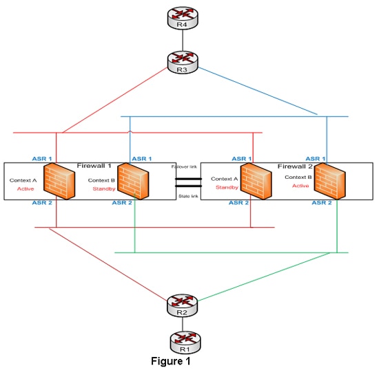
1.1.c (iii) Asymmetric routing
·
In Asymmetric routing, a
packet traverses from a source to a destination in one path and takes a
different path when it returns to the source
·
can cause problems with
firewalls as they maintain state information.
reference:http://www.cisco.com/web/services/news/ts_newsletter/tech/chalktalk/archives/200903.html
reference:http://www.cisco.com/web/services/news/ts_newsletter/tech/chalktalk/archives/200903.html
What is Asymmetric Routing?
Issues to Consider with Asymmetric Routing
Designs Options for Support of Asymmetric Routing in Firewalls
Summary
1.1.c (iv) Impact of micro burst
·
Micro-bursting - rapid
bursts of data packets are sent in quick succession, leading to periods of full
line-rate transmission that can overflow packet buffers of the network stack
·
Can be mitigated by a
network scheduler
Microbursts are patterns or spikes of traffic that take place in a relatively short time interval(generally sub-second) causing network interfaces to temporarily become oversubscribed and DROP traffic. While bursty traffic is fairly common in networks and in most cases is handled by buffers, in some cases the spike in traffic is more than the buffer and interface can handle.
Typical monitoring systems pull interface traffic statistics every one or five minutes by default. In most cases this gives you a good view into what is going on in your network on the interface level for any traffic patterns that are relatively consistent. Unfortunately this doesn’t allow you to see bursty traffic that occurs in any short time interval less than the one you are graphing.
The first place you might notice you are experiencing bursty traffic is in the interface statistics on your switch under “Total Output Drops”.
R2#sh int f0/0 | inc Input
Input queue: 0/75/0/0 (size/max/drops/flushes); Total output drops: 7228
If you are seeing output drops increment, but the overall traffic utilization of that interface is otherwise low, you are most likely experiencing some type of bursty traffic.
No comments:
Post a Comment